Pypilot user manual This manual focuses primarily on using pypilot with the tinypilot image and a Pi Zero dedicated exclusively to autopilot, as originally designed for stable and power-efficient operation. This configuration, similar to the one offered in stores, nevertheless offers numerous control and communication options with applications in software suites running on a separate Pi 4 or 5.
Pypilot Workbook This guide is essential if you want to run pypilot with Openplotter or BBN on a Pi 4 or 5 and want to explore tinypilot in depth. It helps you understand the interactions between the applications and how to configure the Pi, pypilot, and these applications..
This diagram shows how to build your own Pypilot autopilot computer. The minimum configuration required is a Pi Zero W connected to an IMU module and a motor controller. The diagram also shows how to connect an LCD display, an NMEA interface, or a keyboard.
Links to download the tinypilot image with the latest stable version of Pypilot :
- Sean's image version 56 with a tinycore system version that works with RPI Pi 0, 1, 2, 3, or 5 (not compatible with Pi Zero 2W and 3+) tinypilot_2024_07_17.img.xz
- Image version 56 provided by Stellian with a more recent tinycore system version, compatible with all PI http://popies.net/pypilot/tinypilot13-20240915.img.xz
If there are any issues displaying the magnetic heading, it is recommended to check that the .pypilot/hat.conf file correctly specifies the LCD display and IMU being used.
Recommended Use of Pypilot and the Controller
Pypilot motor controllers must be paired with an autopilot ECU such as a Raspberry Pi 0, 1, 2, 3, or 5 running Pypilot, with or without a MacArthur HAT.
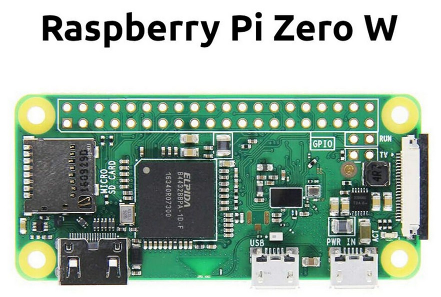
Pypilot was designed by Sean d'Epagnier to consume very little power and be fully operational when installed on a small Raspberry Pi Zero W.
Comparative 12V power consumption of the Raspberry Pi alone:
- Raspberry Pi Zero W : 60mA
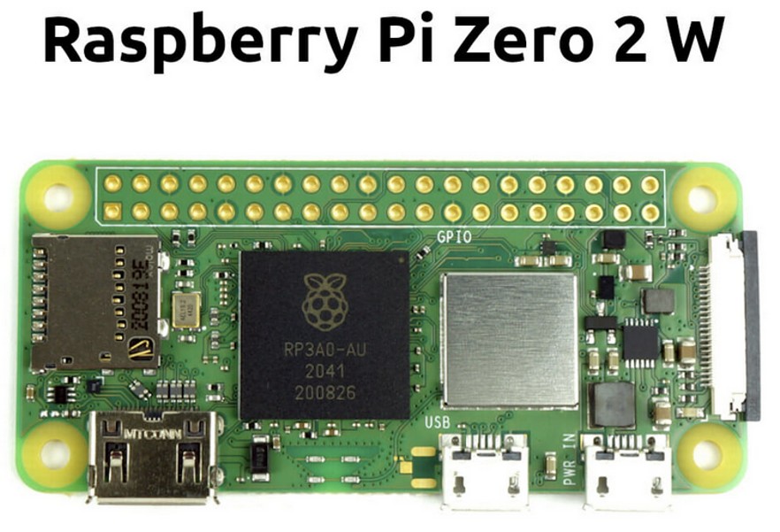
- Raspberry Pi Zero 2W : 140mA
- Raspberry Pi 3 B : >200mA*
- Raspberry Pi 4B : >250 mA*
* Not including the power consumption of the often essential display, other devices connected to the Raspberry Pi, and other applications running simultaneously.
Pypilot can run alongside other applications on a large Raspberry Pi. There are some great nautical application suites like OpenPlotter or Bareboats Necessities (BBN). Both include pypilot among many other applications. While this is informative and interesting, it's a bit like using your desktop computer as your boat's autopilot. Using an SD card as the Raspberry Pi's drive carries a high risk of damaging the file system and applications if a power outage occurs in the middle of a write, before all applications have completely stopped. Installing an SSD hard drive can avoid these problems. However, with these suites, there's still the problem that updates to certain applications can sometimes prevent the autopilot from working.
Your autopilot will be much more reliable, robust, and energy-efficient if you directly connect the controller and an IMU* to a tiny Raspberry Pi Zero W or Zero 2W with the tinypilot image file installed on the Pi Zero's micro SD memory card.
Installing pypilot on a small Raspberry Pi Zero W dedicated to the pilot with the tinypilot image on the SD card
Tinypilot is a downloadable image file that easily installs onto a 16GB microSD card using the Raspberry Pi Imager app.
There is a separate image for the Pi Zero W (dual-core) or Pi Zero 2W (quad-core). See the download links at the top of the page.
There is a separate image for the Pi Zero W (dual-core) or Pi Zero 2W (quad-core). See the download links at the top of the page.
We then have on the SD card all the pypilot files configured to allow a quick startup and a robust lightweight Tinycore Linux system.
the lightweight Tinycore Linux system allows the Pi Zero to automatically run the pypilot autopilot, its IMU, its LCD display, its Wi-Fi router, and its web server upon power-up.
It doesn't do anything else.
It doesn't do anything else.
There's no point in adding a keyboard or connecting a display to the Pi Zero's HDMI output because the lightweight Linux system doesn't allow them to be used to navigate the graphical pages of pypilot.
Connecting a JLX12864 LCD display to the Pi Zero is however useful for viewing the driver status (compass heading, setpoint, parameters).
If you want more graphical capabilities, you'll need to use any other device with a web browser, connected via Wi-Fi to the Pi Zero with the tinypilot image on its SD card. You can also use another Pi with a full Linux system to run the OpenCpn pypilot plugin or to run the pypilot scripts for control (pypilot_control, pypilot_calibration, pypilot_scope).
The main "pypilot" script, which runs automatically with tinypilot on the Pi connected to the motor controller, obviously no longer needs to be run on other devices.
After powering on, pypilot runs entirely from RAM. This allows you to stop the autopilot with the switch on the boat's electrical panel, without the risk of damaging files on the micro SD card. In addition, by installing a stable Tinypilot image, you can be sure that the installed file system has already been tested by many users and will remain intact until you install a new version of the Tinypilot image.
Even if there is a malfunction or problem with the RPI 3, 4 or 5, the autopilot installed on the Pi Zero with tinypilot will still work. By choosing a pypilot computer equipped with a Pi Zero, an additional AtMega328P (arduino) and a 433MHz receiver, the autopliot can even be additionally controlled by waterproof 433MHz remote controls that can be easily found on the internet for a few euros.
Above you will find the link to the diagram of a simple calculator to use tinypilot, showing what is essential and what is optional.
If you choose to use TinyPlot on a Pi Zero, the Pi Zero's 5V power supply will be safer and more robust if you power it with 5V from the motor controller with a micro USB cable (optional for 15A controllers). Simply connect the micro USB connector of the cable to the header marked "PWR IN" on the Raspberry Pi Zero, or even the one marked "USB" if it is not used to exchange NMEA0183 data. To avoid the false contacts that we sometimes have with microUSB sockets, it is even better to supply the Pi Zero directly with 5V (+5V on pin 2 or 4 and GND on pin 6).
If you find the startup too slow, especially that of the web control interface, you can install a Raspberry Pi Zero 2 W instead of the Pi Zero W. But, this will be at the cost of higher power consumption (about 140 mA in 12V instead of 60 mA), without improving the operation of the autopilot. You should know that when starting pypilot, it is only when the autopilot is operational that the wifi and the web server are started, which is wise.
*IMU (Inertial Mouvment Unit)
The IMU is an attitude sensor, like those found in cell phones and drones.It is called a 9-axis sensor because it integrates 3 magnetometers, 3 accelerometers and 3 gyrometers, each of these 3 sensors in each of the X, Y and Z axes. Pypilot uses these 9 sensors to accurately calculate magnetic heading, roll, and pitch with magnetical 3D compensation to maintain accuracy, even when heeling in heavy beam seas.
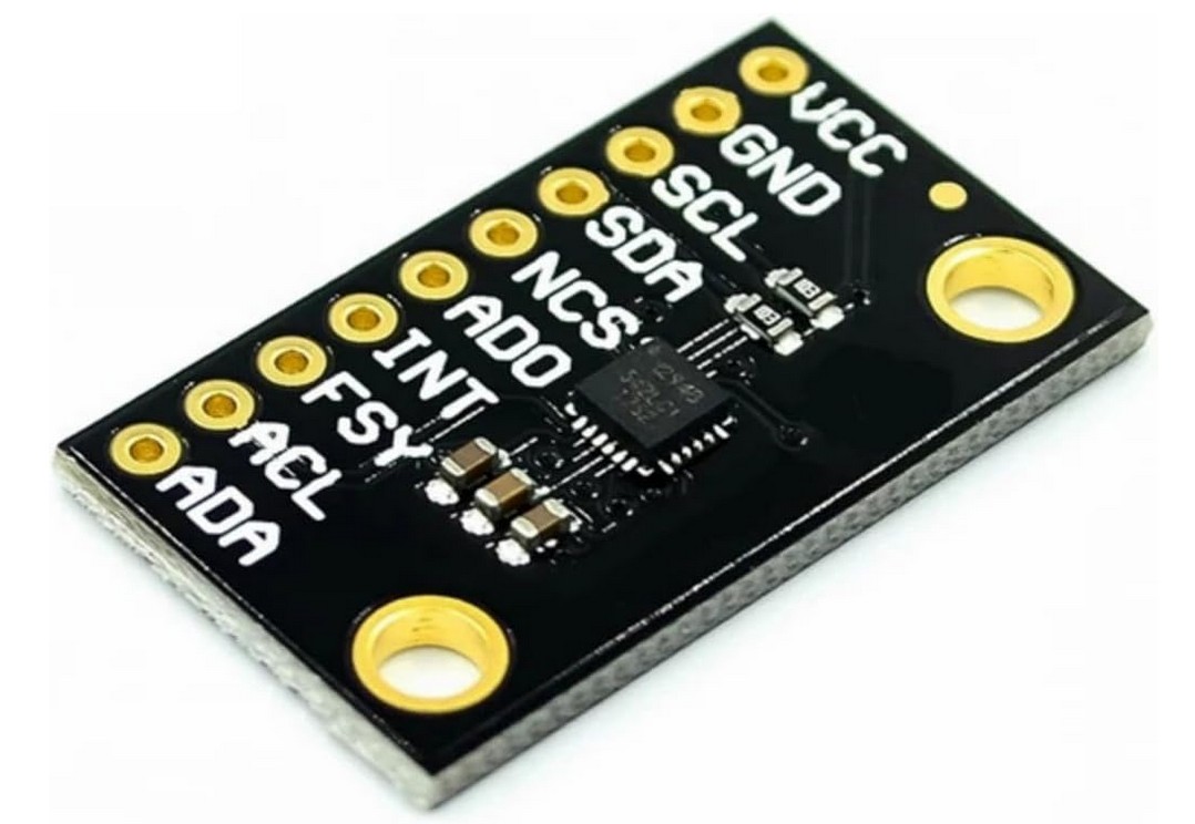
Sean d'EPAGNIER, the designer of pypilot, recommended an IMU module based on the MPU9255 or MPU9250 chip. These modules, sometimes of very uneven quality and performance, were all directly compatible with the Raspberry Pi's 3.3V (3-wire) I2C bus. Since then, to achieve greater battery life, phones now operate at 1.8V. The MPU9255 and MPU9250 chips are becoming increasingly rare. They are increasingly being replaced by the ICM2948 chips with a 1.8V I2C bus. Unfortunately, this bus cannot be connected directly to the Raspberry Pi's 3.3V I2C bus. However, the ICM20948 chip is of much higher quality and consumes less power.
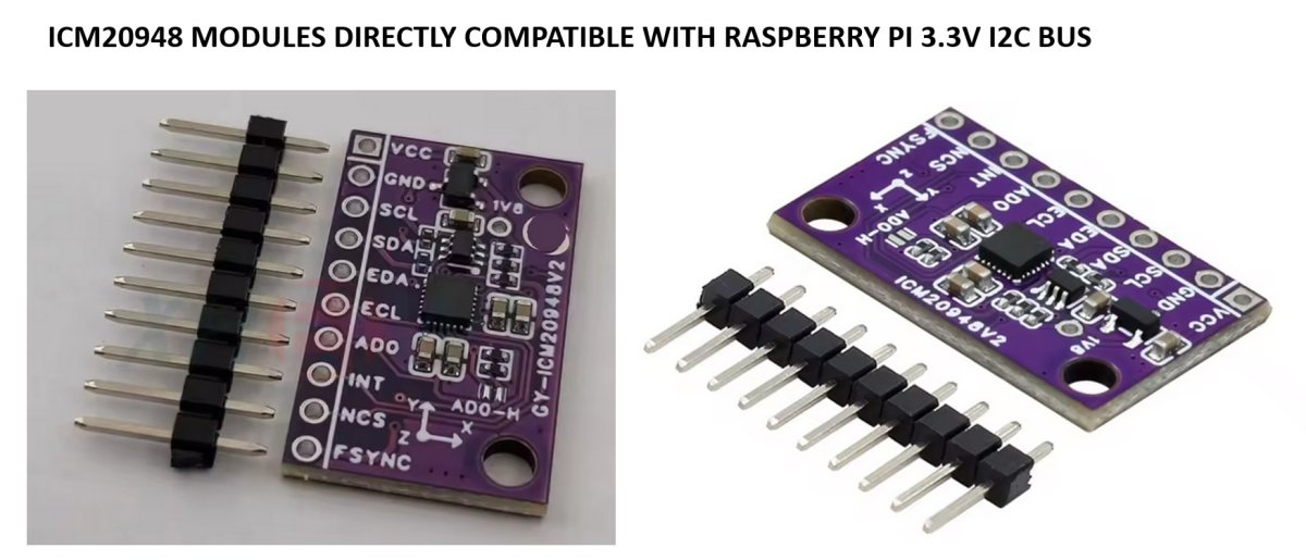
It's important to note that ICM20948 modules with only a few components, in addition to the ICM20948 chip cannot be directly connected to a Raspberry Pi's I2C bus, even though they can be powered by 3.3V or 5V according to the vendor, which is true but misleading. The ICM20948 chip can indeed be powered by 3.3V or 5.5V, but this is not the case for its I2C interface which has a separate power supply at pin 8 of the integrated circuit. According to the IC manufacturer, TDK, this should not be powered at more than 1.95V. Fortunately, there are more and more ICM20948 modules that are directly compatible with Pis and Arduinos. They are no more expensive, but they also include a 1.8V regulator to power the I2C interface of the ICM20948 integrated circuit, as well as a few additional components to adapt the ICM20948 chip's 1.8V I2C bus to the I2C bus of the Raspberry Pi (3.3V) or Arduino (5V).
In electronics, exceeding the manufacturer's limits can strangely not be a problem under certain conditions. But this means accepting the risk of malfunction with other operating temperatures or voltages. It is therefore prudent to install an ICM20948 module with an I2C bus compatible with that of the Pi. For example, there are modules designated ICM20948V2 or GY-ICM20948V2, which are suitable for the Pi.
The Navitop computers integrate all IMU components directly onto their printed circuit boards (TDK ICM20948 sensors, 1.8V power supply circuit, and I2C bus interface circuits).